Mike Anderson's Pico Canyon Steam Engine Restoration Project
In 2012, Mike Anderson bought a Farrar & Trefts steam engine that was salvaged from Pico Canyon that he plans to restore. His engine came from Bob Hughes and his father, John Hughes. Bob and John helped out in Pico and Wiley Canyons removing iron with Greg Johnson in 1974-75. Bob and Greg are about the same age. The engine was owned by Bob originally but ended up at his fathers place. After John passed away 2-3 years ago, Ron Haskell ended up with it. Ron had no interest in the engine so he sold it to Mike.
On this webpage, we will follow the progress of Mike's restoration project from unloading at his house to (hopefully) a running steam engine. This project will take years, depending on how much time Mike has to work on it, so I will be adding images a little at a time.
In 2015, Mike purchased a second Farrar & Trefts steam engine. The restoration for that engine will also be followed below in the proper time sequence.
Before we get started, it might be helpful to look at plans of a stationary steam engine, plans of the engine cylinder, and an engine schematic.
All the images and captions were provided by Mike (although I may clarify some of the captions). I appreciate the time and effort that he took to do this.
COPYRIGHT NOTICE: All these images are owned by Mike Anderson and are used with his permission. They are not in the public domain.
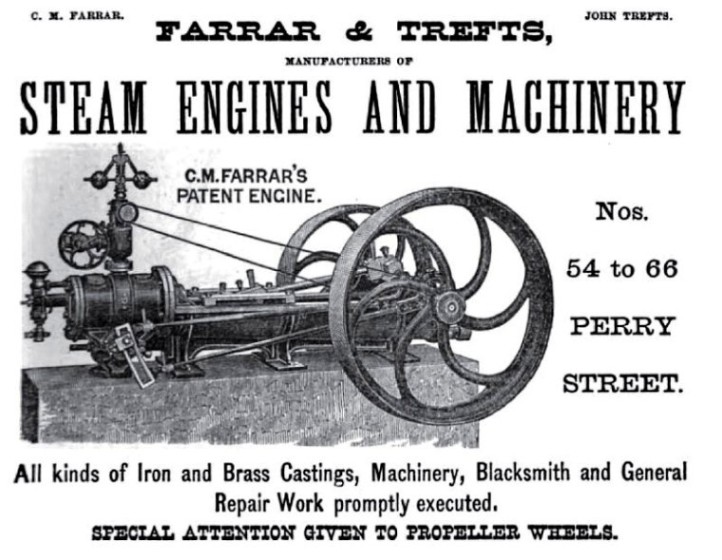
Old Farrar & Trefts advertisement. The engine shown above is similar, but not quite the same as my engine. Farrar and Trefts were Chilion M. Farrar, 1830-1907, and John Trefts, 1818(France)-1900. Here is Farrar's 1871 engine patent and his 1872 patent, an improvement on the 1871 design.
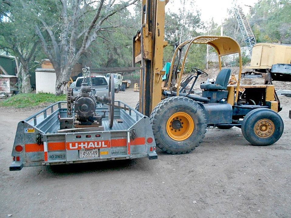
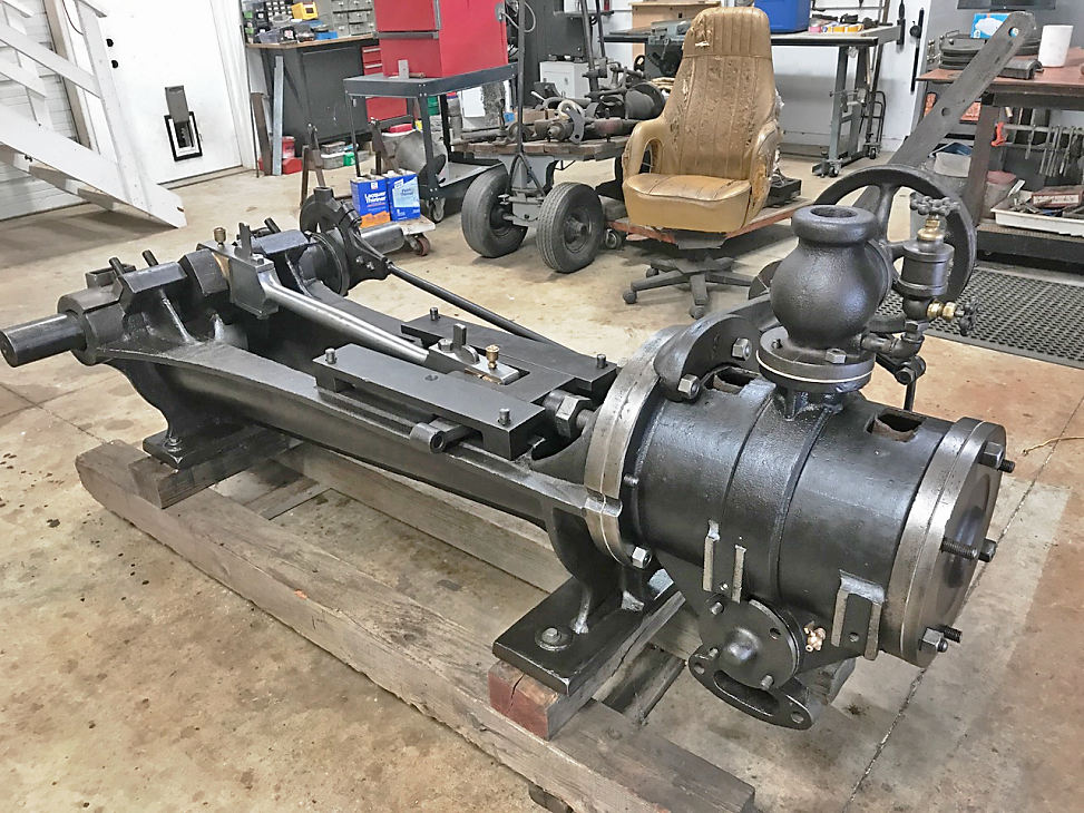
11/24/2012 - Unloading the engine at my house in 2012.
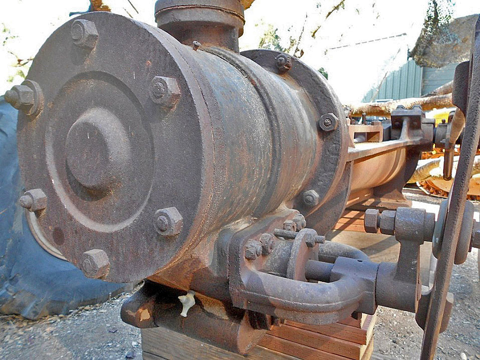
Here is my engine just after I brought it home. The Stephenson's valve linkage and crank rod are disconnected.
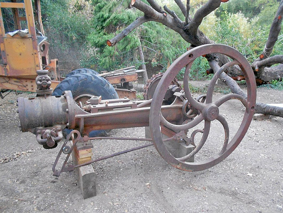
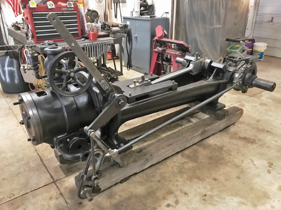
Another view, with the linkage in place.
Crank end of the F&T engine. The eccentric cams for the Stephenson linkage are between the flywheel and the right hand crank main bearings. The crank main bearings are poured in place babbitt, adjusted for wear with the double nuts on the bearing journals. The rod bearing at this end and at the cross slide end are bronze or brass and, like the previous photo, you can see the wedge used to tighten the bearing as it wore. I'm sure there was once a brass drip oiler on the bronze bearings threaded into the hole you can see, like
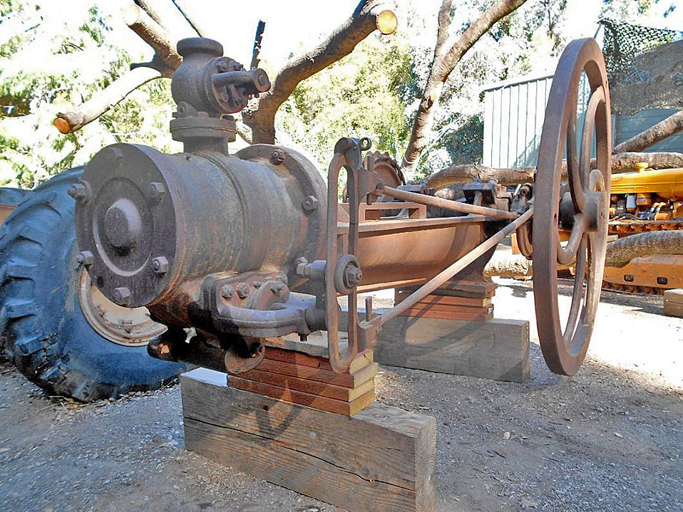
these. You can see on the far side of the left main bearing, beyond the double nuts, the rectangular cups with hinged lids that were used to hold a reservoir of oil for the main bearings. There are similar cups, but without lids on the valve eccentrics. There was probably a felt pad in all of those reservoirs to hold the oil and/or keep dirt and rain out of the bearings.
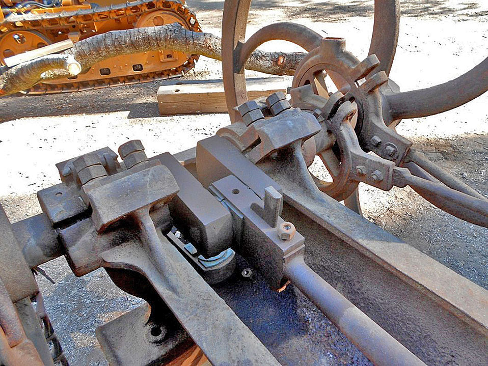
Close up of the valve end of the Stephenson linkage used for determining direction of engine rotation. The video here explains the operation on a sliding valve whereas the F&T uses a semi-rotating valve. The principle is the same. Some of the engines and parts in Pico Canyon at the school house had an extension on the cylinder casting to accommodate a lever system for changing the linkage position. The Pico Canyon engine at the Antique Gas and Steam Engine Museum has that mechanism. The wedge shaped pieces held in place by the square headed set screws are used to tighten the bushings at the pivot points when they become worn. You can also see a similar wedge on the big end of the rod bearing in the photo above. The crack on the slotted section will need to be welded.
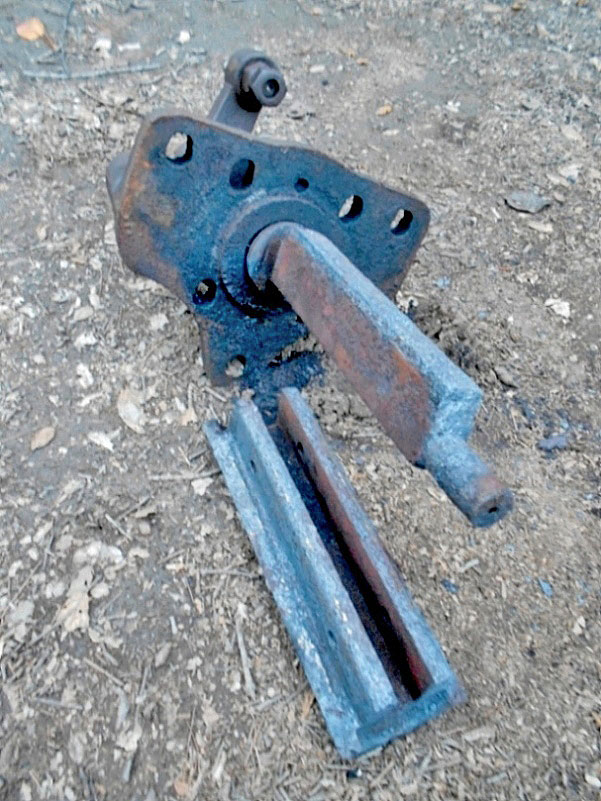
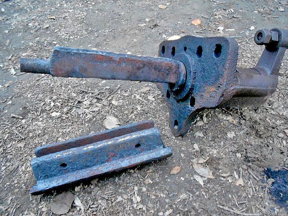
Packing gland at the bottom of the cylinder and piston rod on the left. The crank rod, cross slide end, was detached from the cylindrical section on the right when I got the engine. The flywheel and crank would turn, but the cross slide and piston were stuck, as was the semi-rotating valve. The Stephenson linkage with the broken piece at the valve end was probably cracked when the crank was rotated after the rod was dropped. The flywheel may have been forced to move, with the eccentrics putting huge forces on that casting, cracking it. According to Greg Johnson, valve linkage damage to a lot of old engines that have been rusted and stuck is quite common. Somewhere along the line someone tries to rotate the flywheel, cracking parts that weren't designed for such loads. The end of the cylinder rod is threaded and the nut you see would have locked it into position on the cross slide.
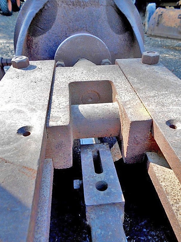
Looking towards the cylinder, with the cross slide and guides. The crank rod has been dropped and is resting on the bottom of the main body casting. The slot is where the bearing wedges should go, they were missing. The bronze bearing and it's keeper had been removed and was laying on the bottom. The cross slide would have had babbitt where it makes contact with the main frame and the guides, but most of that was melted out from fires in Pico Canyon. The cylindrical part where the crank bearing would be attached is part of the cross slide casting... I have no idea how this could have been machined round! The countersunk (beveled) holes on either side of the guides would have been for oiling the cross slide wear surfaces. You'd think they would have had oil drippers there, but I don't see any threading to mount them. The lateral forces on the cross slide would be pretty minimal so maybe they didn't wipe the oil off too quickly and drippers were unnecessary.
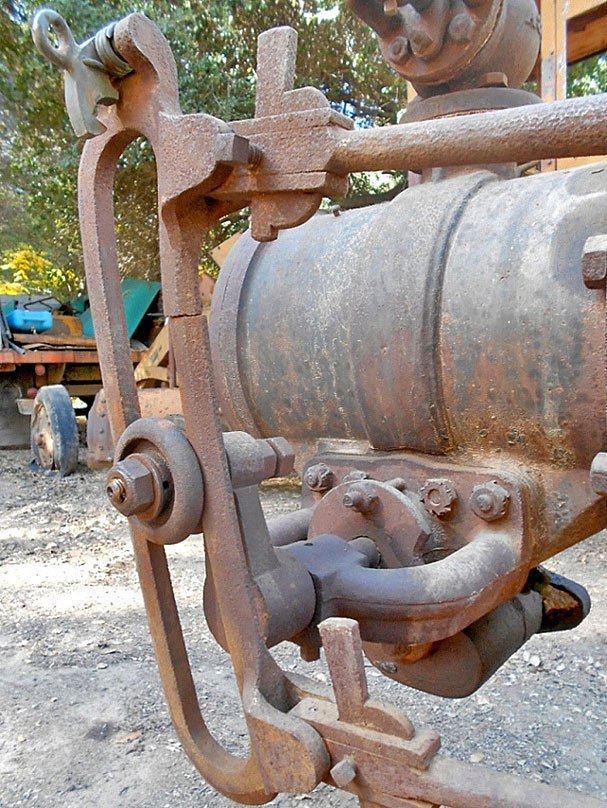
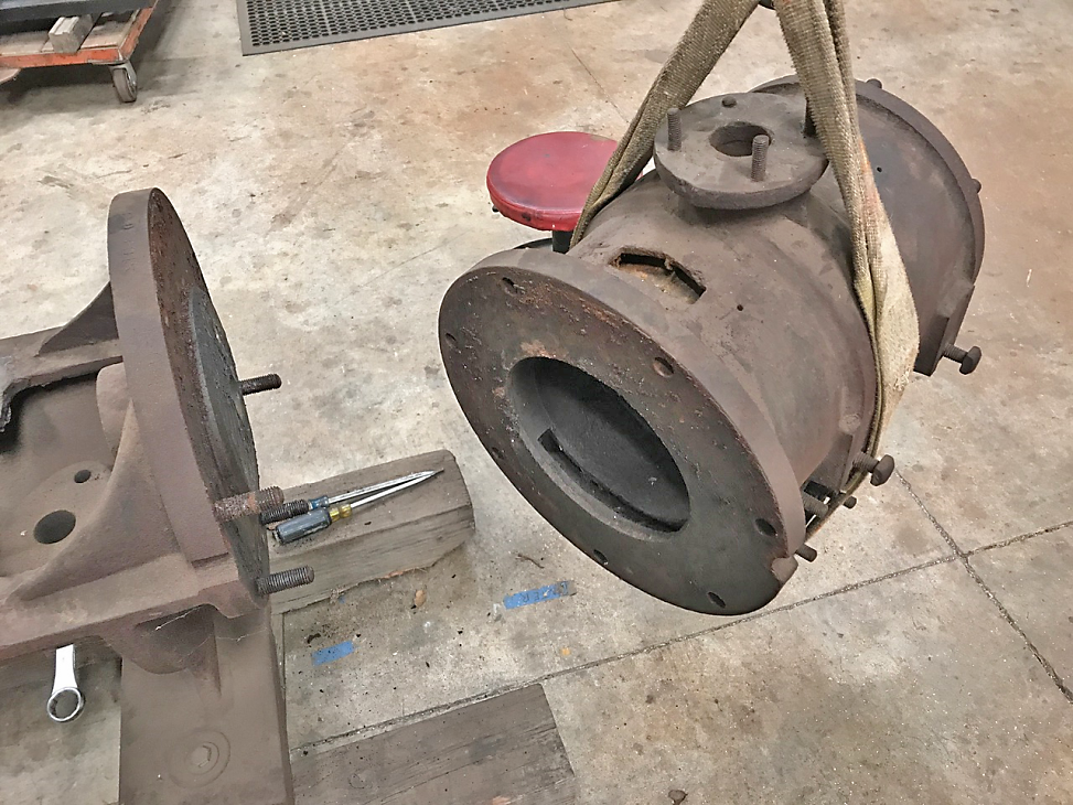
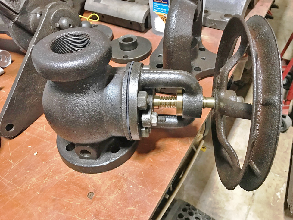
Close up of the semi-rotary valve; it just rocks back and forth to direct both exhaust and high pressure steam into and out of one end of the cylinder or the other. The large part of the casting hanging below the valve chamber is the exhaust steam collector and would have had another casting to bolt on the left side that would have allowed a pipe to be attached. That piece was missing from the engine. The valve was quite stuck, as you will see in the next photos. The small brass petcock would have been used to drain water from the valve chamber and cylinder if necessary. It's not obvious in this photo, but the outboard valve bearing, where you can see the small oil hole, is a bronze bearing and replaceable if worn. The raised "bulge" around the cylinder is where the inlet steam at the top main inlet valve, just out of sight in the photo, would go around the cylinder from above and into the valve chamber below. There is a "dead air" space on either side of that central bulge as there is a hollow space between the exterior of the cylinder, the part you see, and the inner part of the casting where the bore is. The small screw visible near the top of the cylinder would have held one of two name badges that also covered the holes that would have supported the core "print"; the print is the part of the sand core that would have been outside the cavity to support the sand core as it was suspended in the void which would be filled with the molten metal to make the part. "Freeze plugs" on an automobile engine are actually holes that would have been part of the print to hold the sand cores that make all the hollow parts of the engine block where the coolant flows, among other things. Here, that dead air space probably functioned as insulation to help keep the cylinder hot so the steam would condense less when it was introduced. Some early steam engines have wood insulation on the outside of the cylinder to serve the same purpose. Greg Johnson has at least one engine with wood on the outside.
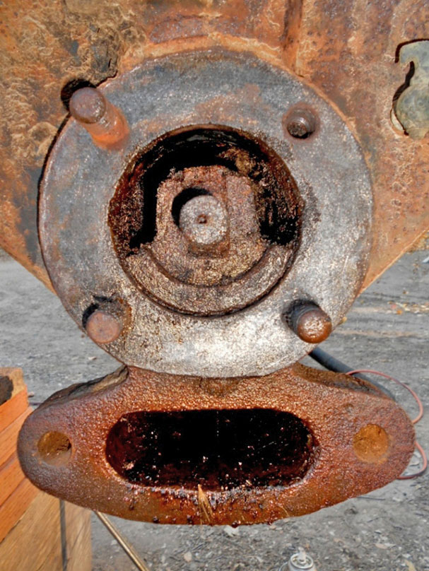
The cap or cover on the far side of the valve (away from the linkage) has been removed, and some of the mouse crap/debris removed to show the parts. The cover also supports the outboard end of the shaft. The vertical rectangular section visible above and below the protruding round bearing surface is part of the shaft and was a loose fit in the slot milled into the valve. Steam pressure in the cavity surrounding the valve would have forced the valve against the round bore in the cylinder casting. The small crank arm on the opposite side would rotate this assembly a few degrees in both directions as the valve cam eccentrics would push and pull on that crank arm, exposing ports seen in the photo below. It happens to have been "parked" in an almost neutral position, blocking both input and exhaust ports. This no doubt kept a lot of debris, and mice, from entering the main cylinder, but as you'll see, didn't keep moisture out.
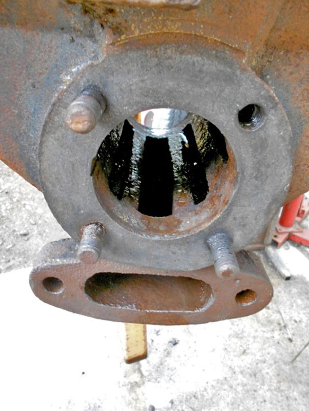
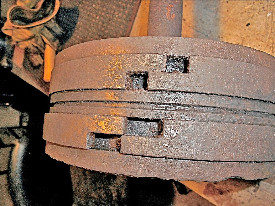
Valve parts have all been removed and the bore cleaned up a bit here, showing the ports. The central slotted port goes directly into the large exhaust chamber below. The oval opening below with the two outboard holes is where a missing casting with a large pipe thread would have been bolted to carry the spent steam back to the boiler. The two slotted ports on either side of exhaust port go directly to the far ends of the main cylinder to introduce high pressure steam into the main cylinder via passages cast into the cylinder during the power stroke and bring back the exhaust steam on the opposite end of the main cylinder. This action or direction, of course, then reverses as the piston reaches the end of a stroke and the valve timing rotates the valve in the opposite direction. When the valve is at maximum rotation one entire side port is exposed allowing the high pressure steam to flow directly into one end of the main cylinder while sealing the opposite port against the high pressure steam while positioning the groove in the valve (shown in photos to come) to allow exhaust from the opposite side main piston to be directed into the central exhaust port. There appears to be another set of ports beyond the cylinder ports, but they are dead ends, going nowhere and just part of the main casting and probably only there to keep wall thicknesses consistent, which would aid in the casting process. You can only see one of these, on the right side, in this photo. The main bore here will need to be bored oversize to get rid of the deep pitting and the valve will need to be machined to fit the new radius.
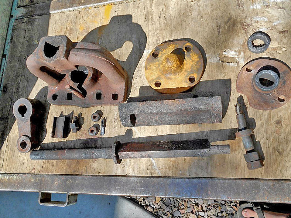
Valve parts. Main parts named (minus bolts/small parts) starting from the crank arm on the left then the top row first and back to the crank: Crank arm, cap and outboard bearing support, end cap and bearing support opposite side, packing compressing sleeve, Stephensons's link attachment pin, valve, and below that the main valve shaft. There may be "trade" names of some of these parts that I don't know... Greg may. The small rectangular part to the right of the crank arm is a bronze bushing that fits into the outboard bearing support and is adjusted with the set screw to the right of it to compensate for wear. The main shaft will need to be thrown out and a new one made due to severe corrosion at the bearing surfaces and also where the packing gland was positioned. It must have collected and held moisture due to the amount of the shaft reduction there. I'll need to make a new link pin because this one is bent... hmmm... I'm guessing that whatever force bent this also cracked the link part mentioned in previous photos.
Depth of field is pretty nasty, but this is the semi-rotary valve after much heat to break things loose. The valve is supposed to slide up and down in the rectangular section of the shaft a small amount. Steam pressure would then keep it tight against the seat of the main cylinder/valve housing casting, even if the oscillating shaft isn't perfectly centered. This would also make it self adjust for wear.
These pieces are pretty severely rusted, as you can see. I believe I'll be able to salvage the valve, but will need to machine a new arced surface to match the new bore on the seat. If necessary, I'll mill the slot smooth then make the mating flat surfaces on shaft sized to be a nice slip fit, since that part will be all new anyway. You can also see how water reacts with steel vs cast iron on these pieces. The valve and mount are cast iron, the shaft is steel and much more severely rusted. I'm not quite sure what the reason is, but steel usually rusts more readily than cast iron does.
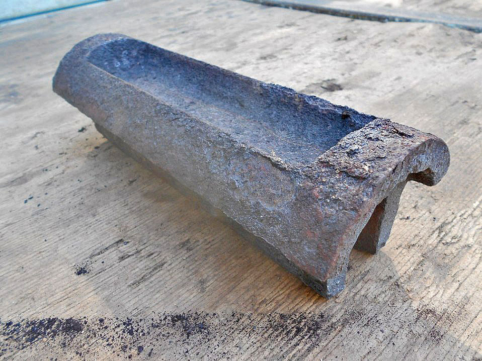
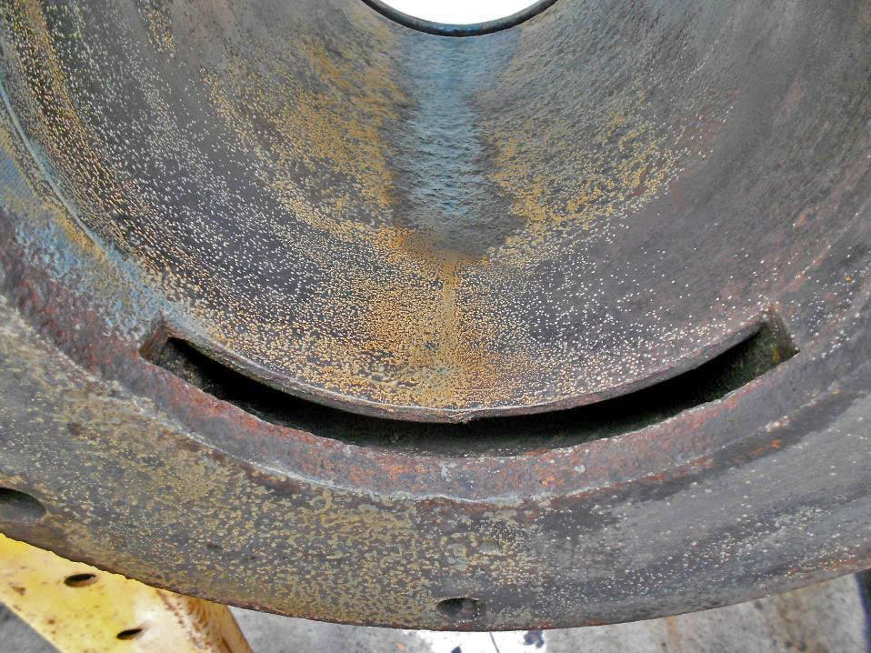
This is the area that will need to be arced to match the new bore for the valve seat. It's in rough shape, but the material thickness is heavy enough that it should be salvageable without too much trouble. The depressed area in the middle of this surface is where exhaust steam is redirected from the main cylinder, through the slots in valve housing and into the exhaust manifold on the underside of the main cylinder casting.
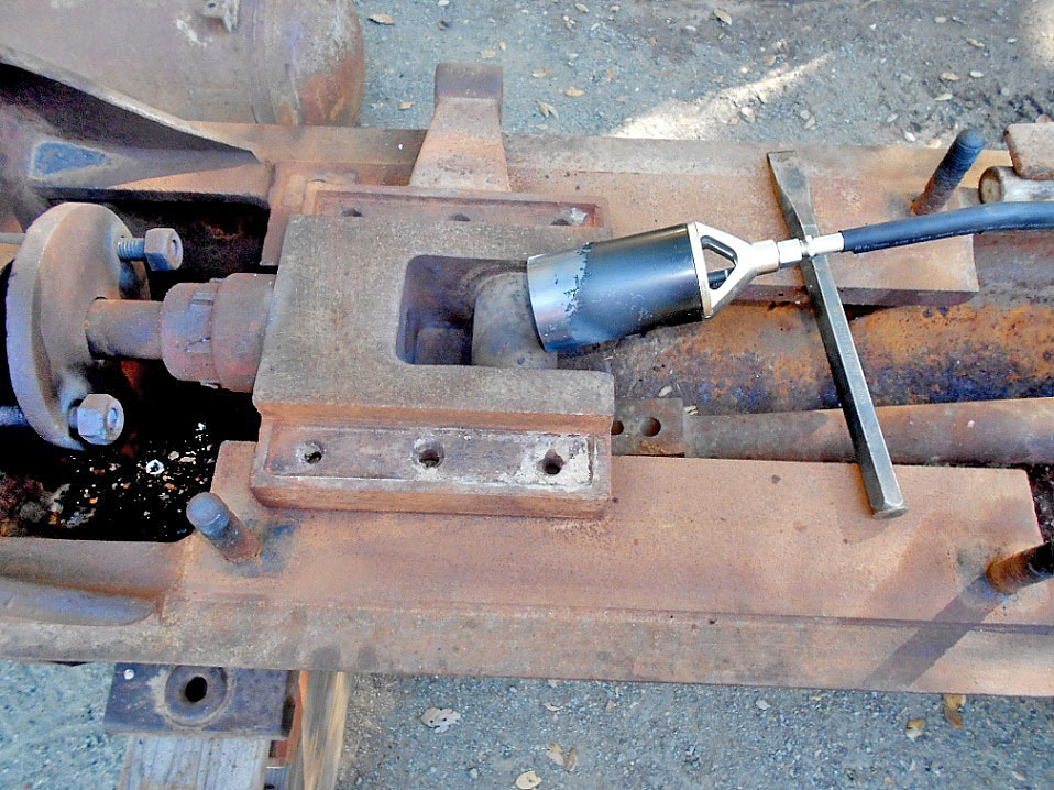
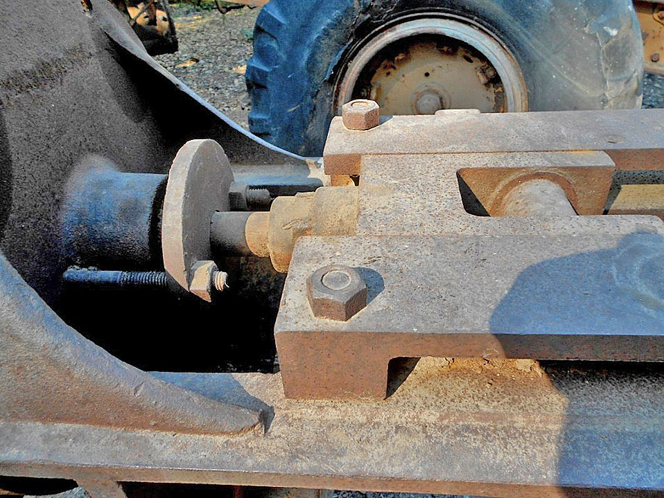
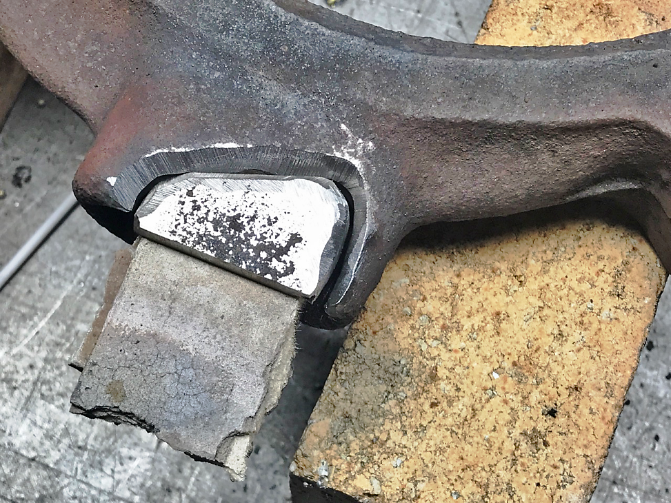
Heating the cross slide casting and the end of the piston rod. The lock nut on the left was very tight and also took a lot of heat to finally loosen. To the left of the nut is the packing gland, where the rod was severely reduced in size due to rust. The crank rod is laying in the bottom of the frame casting on the right. Fires in Pico Canyon had apparently been hot enough to melt almost all of the babbitt that would have been between the cross slide and the frame, and also been on the surface where you see the three holes on either side of the slide. The upper bars that guided the cross slide were fastened in place with nuts on the large bolts near each end of the flat machined surface to capture the slide. The arm part of the cross slide casting, near the top of the photo and extending past the frame, was used to provide motion to a boiler water injection pump. Since the boilers were remote, this feature wasn't used on this engine. The barrel of the pump would have been fastened to flats on the sides of the main cylinder.
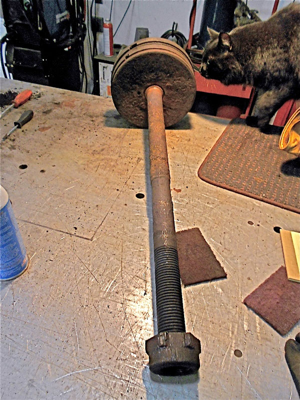
Piston and rod. Here the reduced part of the rod where the packing gland was is quiet obvious. A new rod will need to be made. The top end of the rod is tapered with a nut on the end to hold the piston onto the rod.
The piston is a one piece hollow casting with two cast iron rings. Here you can see the ring gap, spread open since it's out of the cylinder. I'm not sure yet if I'll need to make a new piston or have the diameter built up with metal spray; the amount removed after boring the cylinder will determine how I'll approach making everything fit as it should. It took a lot of soaking with penetrating oil, then lots of heat and finally rigging a hydraulic jack to the end of the cylinder to push the piston loose. I had to work it back and forth many times in order to get it free enough to slide out of the cylinder.
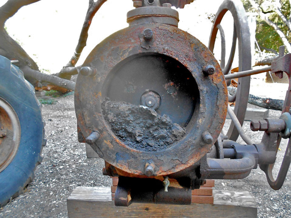
This is the gunk that I found after removing the cylinder head.... not too bad for laying around for 120-130 years, depending on when it was shut down. The piston was pretty happy about it's position and took a lot of heat, plus a hydraulic jack get it to move. You can see two of three brass pipe plugs on the piston to block holes for a core print to hold the sand core that made the piston casting hollow. The center nut tightens the piston onto the tapered end of the piston rod.
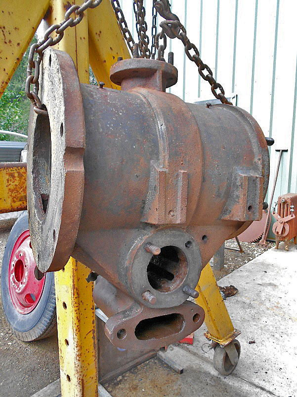
Cylinder with piston out and cylinder removed from the frame. I've needle scaled the worst rust to prep the cylinder for machining. The groove on the perimeter of the flange would have been for clearance of the boiler injector pump rod had one been used. The flat machined bosses on the side of the cylinder would have been for mounting the body of an injector pump.
End view of the main cylinder bore after needle scaling. The slot in the foreground and also at the other end of the cylinder is where inlet/exhaust is introduced/removed into the cylinder. A cast in place passage leads from these into the slots in the valve chamber underneath the main cylinder. The cylinder will be re-bored oversize to clean up the rust pitting. Original bore was 9 inches in diameter with a piston stroke of 12 inches.
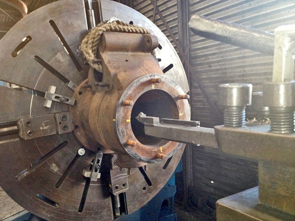
This big cylinder looks small compared to the giant faceplate. The bore was originally 9”; the operator had a couple more passes to make to clean up the rust and pitting. The screw driven clamps both center the casting and grip the perimeter for driving it and the toe clamps hold the casting tight to the faceplate. The machinist said that the squareness of the faces to the bore was within .002” before turning. Boring took place on November 11, 2013.
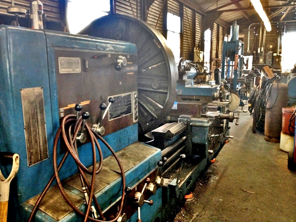
The cylinder is bolted to the other side of the large faceplate/four jaw chuck you see here. I do NOT have a lathe this big at home!
Here is a video taken by Mike of the cylinder being bored.
In 2015, Mike bought another Farrar & Trefts steam engine from Jack Bonano. It was salvaged from Pico Canyon by Greg Johnson and his friends in 1974. One of those friends was Terry Hathaway and Greg believes that Terry took home that engine. He does not know how Bonano ended up with it. This engine is in much better shape then the first one so Mike will now focus his attention on restoring the new engine. However, he will combine some of the work by machining common parts for both engines at the same time. This will make completing the other engine faster when he gets back to it.
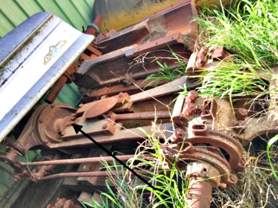
Feb 5, 2015 - Second Farrar & Trefts at previous owner’s property. Arrow points to piston rod.
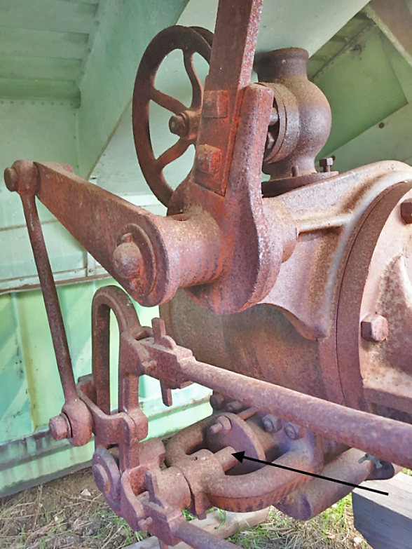
Feb 5, 2015 - Second F&T at previous owner’s property. Arrow points to valve actuator shaft.
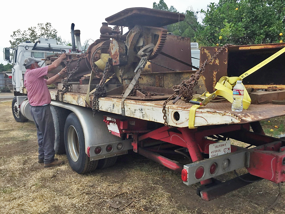
Binding the engine and other items from previous owner’s place. That's Virgil in the photo.
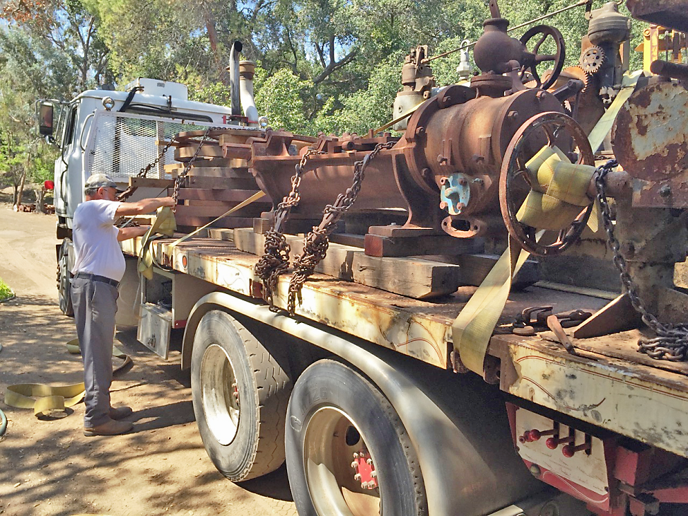
This photo is the engine, and others, as it arrived at my place on 7/19/2015 with Virgil.
After unloading, 7/19/2015, both F & T engines together! First one (from 2012) is disassembled in the background. Newest one in the foreground.
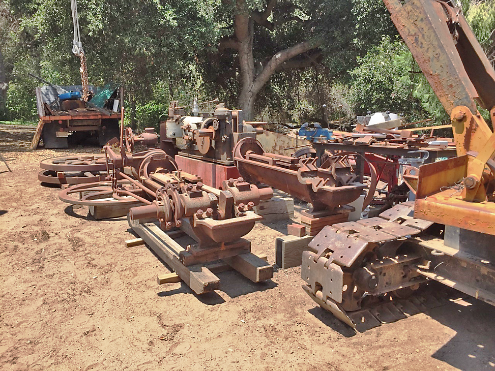
Another view. New engine on left, old one on right. I also bought a Western 30HP natural gas engine, a welding positioner, and a large jib crane from the same guy.
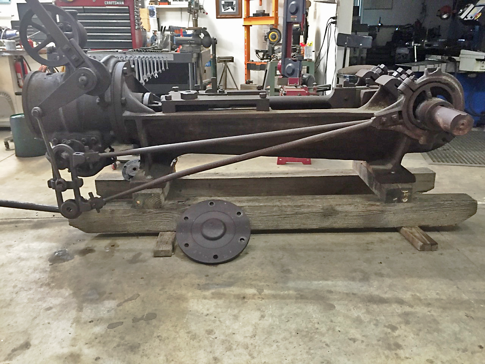
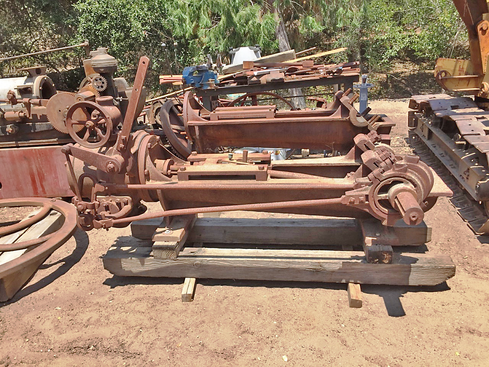
In my shop, starting disassembly of engine 2 on 10/23/2015. I had sprayed an oil/ATF mix on it to start loosening things up, hence the different color from the outside view
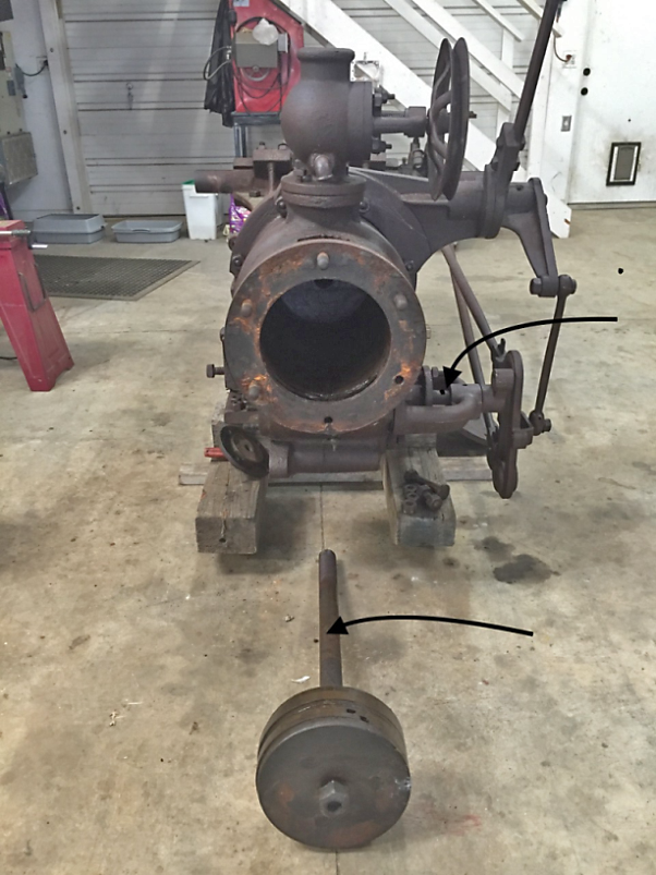
Most of the bolts and parts were easily removed! Arrows to piston rod and valve actuator shaft.
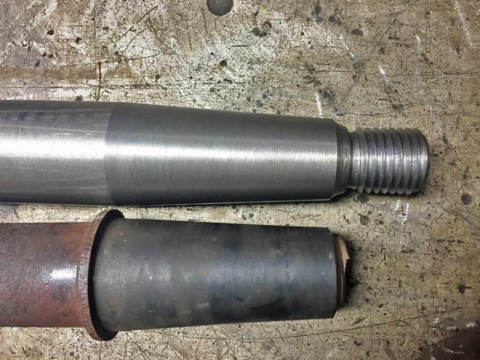
Old piston rod on the bottom, new one on top. Piston end threads broke on both engine’s rods.
Video 1: Beginning of a cut for threading one end of a piston rod.
Video 2: Ending of one of many repeated small cuts to reach full depth for the threads on one end of a piston rod.
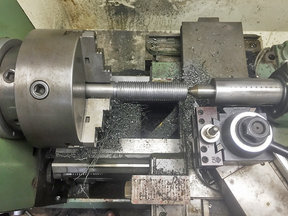
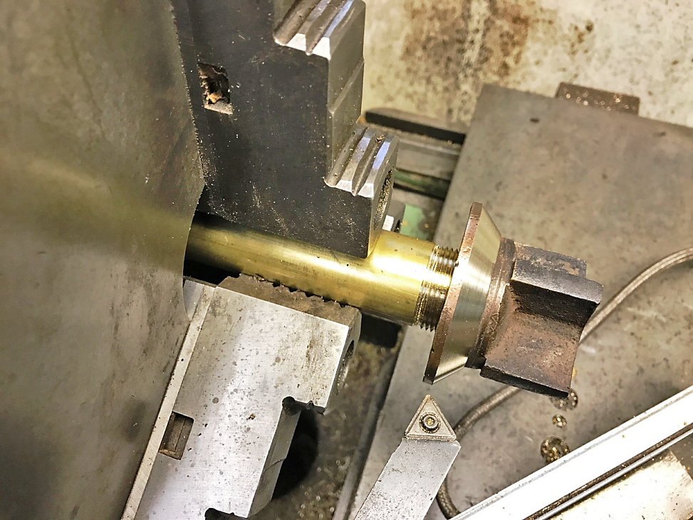
Turning threads on the outboard end of a piston rod. I made two of these because both engines had damage where the packing held moisture, and the piston-end threads had broken when removing the nuts.
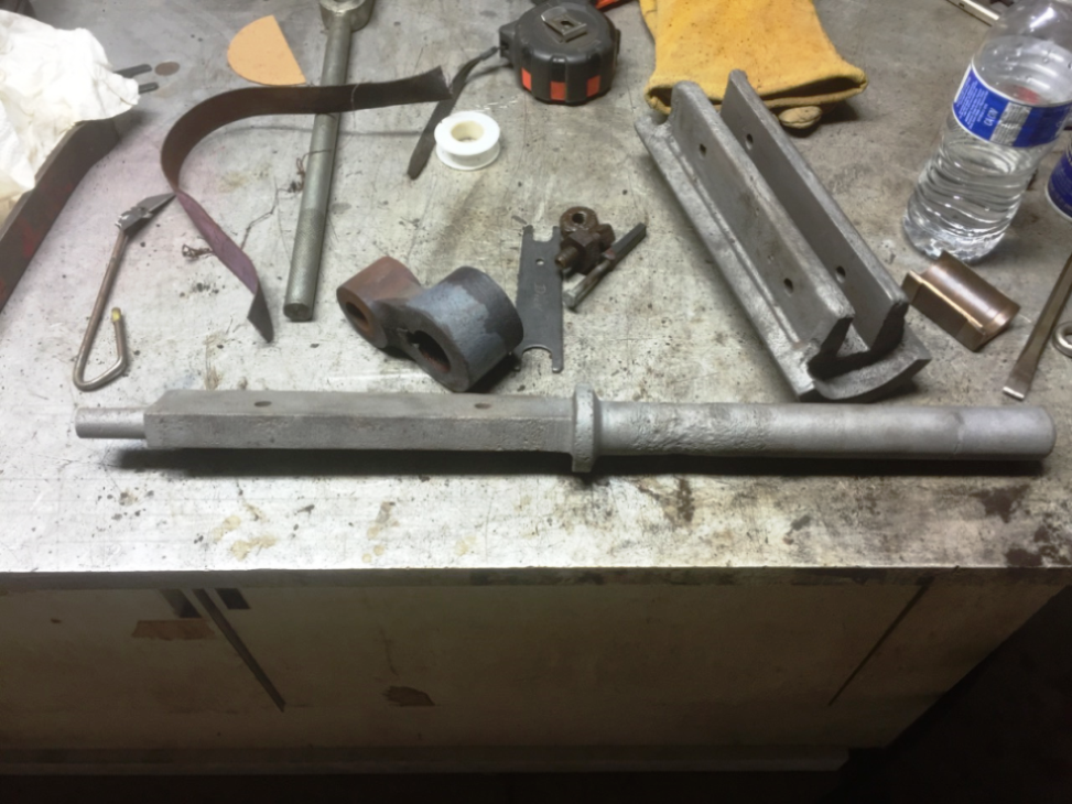
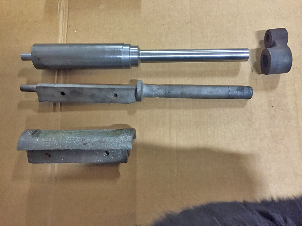
Semi-rotary valve and actuator shaft. New shafts for each engine will be made due to the rust damage, and the valves will be built up by brazing in order to machine them to the new bore in the cylinder.
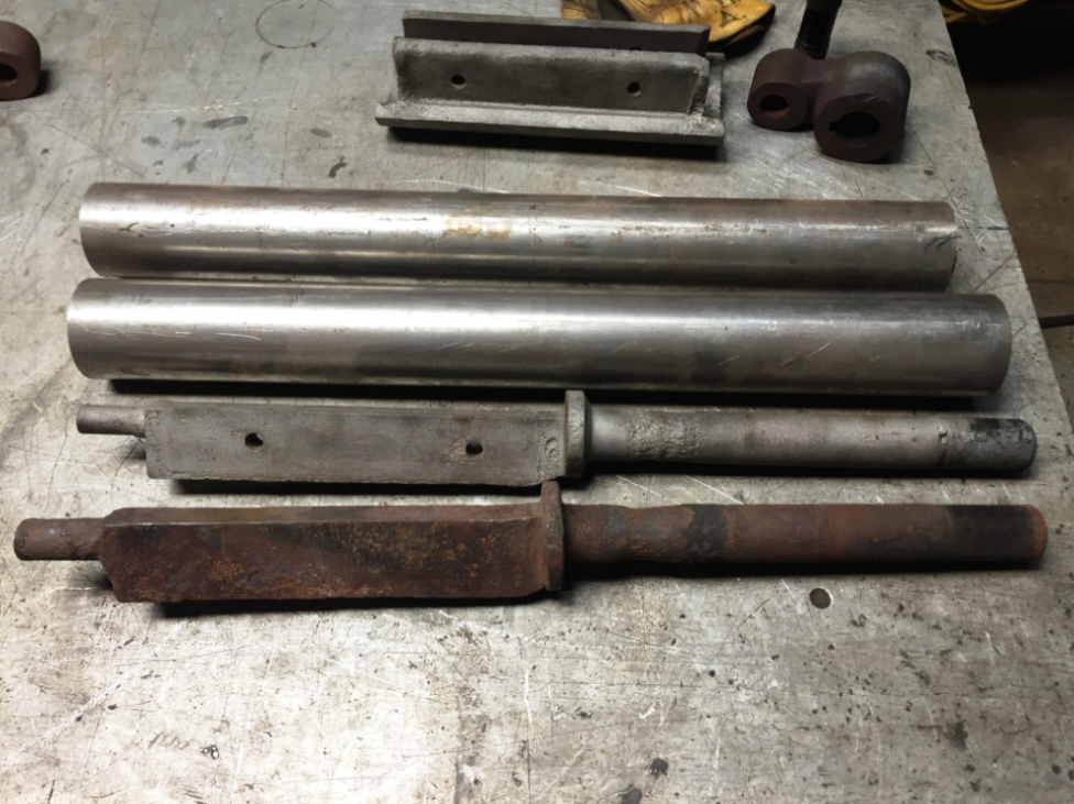
The two actuator rods and blanks for the new replacements.
Lots of material removed!
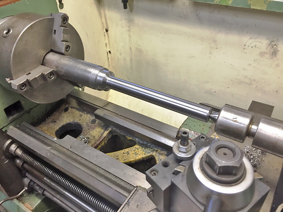
Finished with the lathe work. My CNC mill died before I could complete these…. waiting for repairs to the mill before I can continue. When finished I’ll clamp the valve bodies to the shafts in order to hold them for turning to the new valve bore diameters.
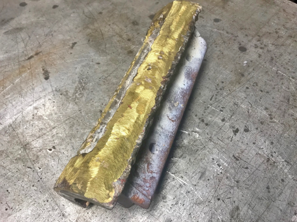
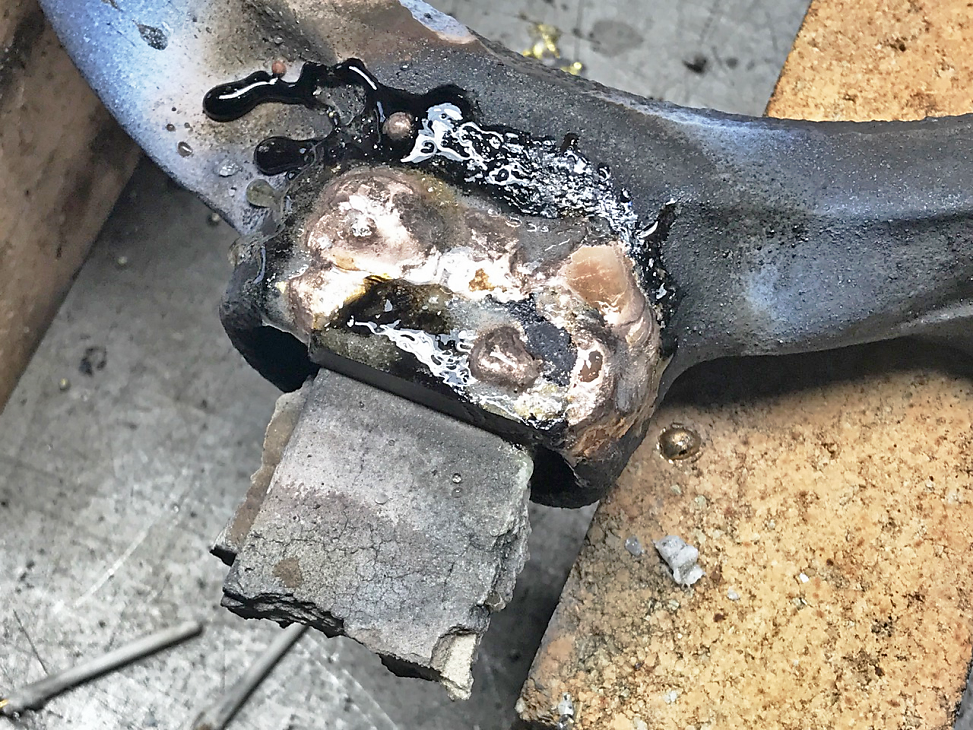
This is the valve body after having it brazed. Looks nasty, but there’s a lot of extra material applied.
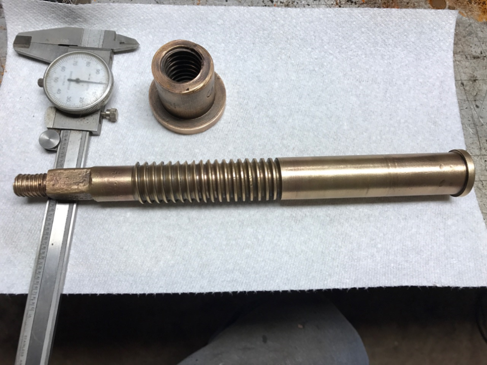
Throttle valve shaft and nut. The seats were so badly worn that such great pressure was used to shut them off that the threads were worn and distorted as you can see on this photo.
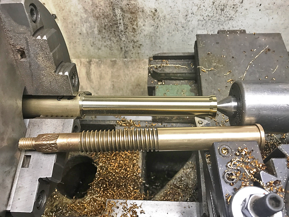
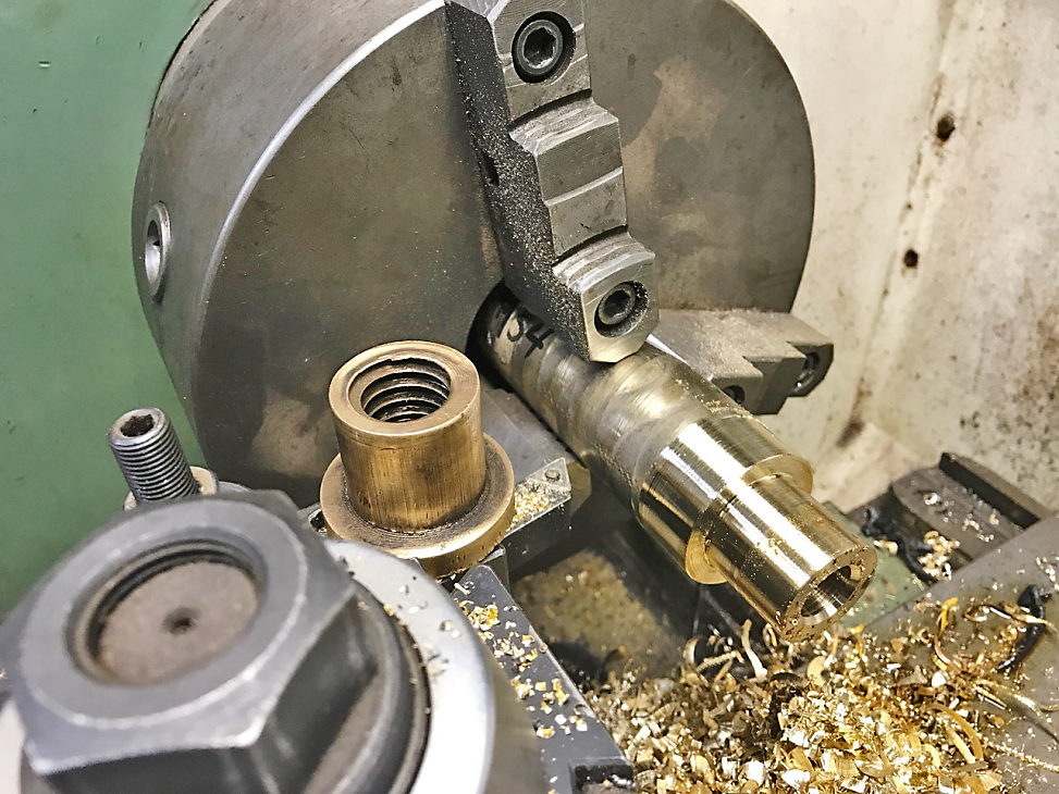
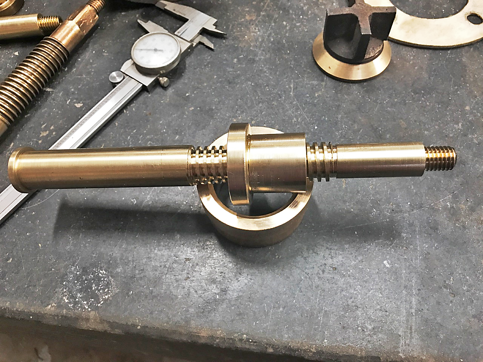
Turning a new shaft for the main valve.
Beginnings of a new nut for a main valve.
I threaded a “dummy” shaft for turning the valve. Both castings were worn but still serviceable after cleaning up the mating surfaces.
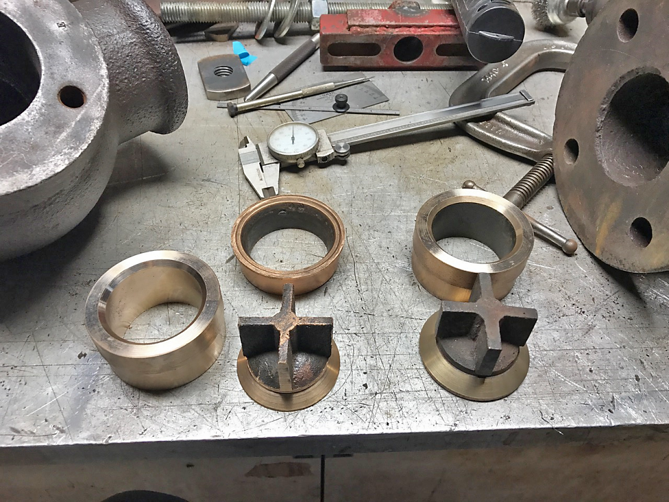
New valve seats and the corresponding parts. Notice the difference of the thickness of the bronze castings…. they’re interchangeable but certainly of different patterns.
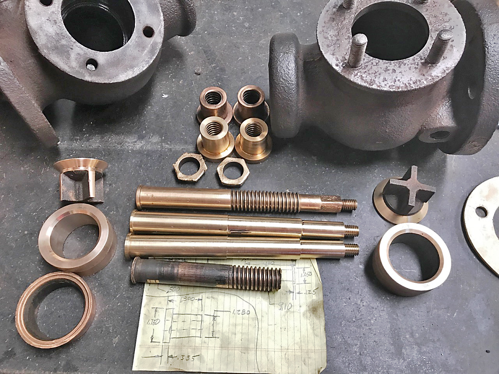
New and refurbished main valve parts, before threading. The hex nuts hold the cast bronze parts onto the shafts.
New parts for the main valve.
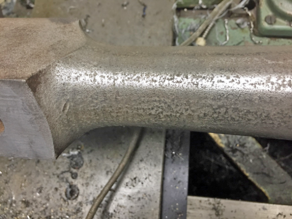
Rust pitting and dings on the end of a connecting rod after a little sanding.
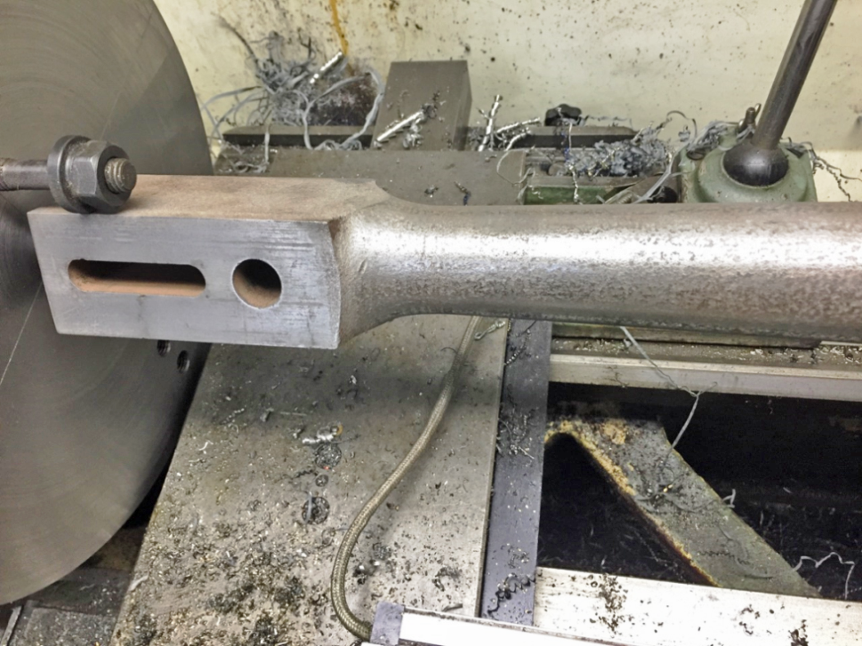
Connecting rod mounted between centers on the lathe, in order to file the connecting rod shaft.
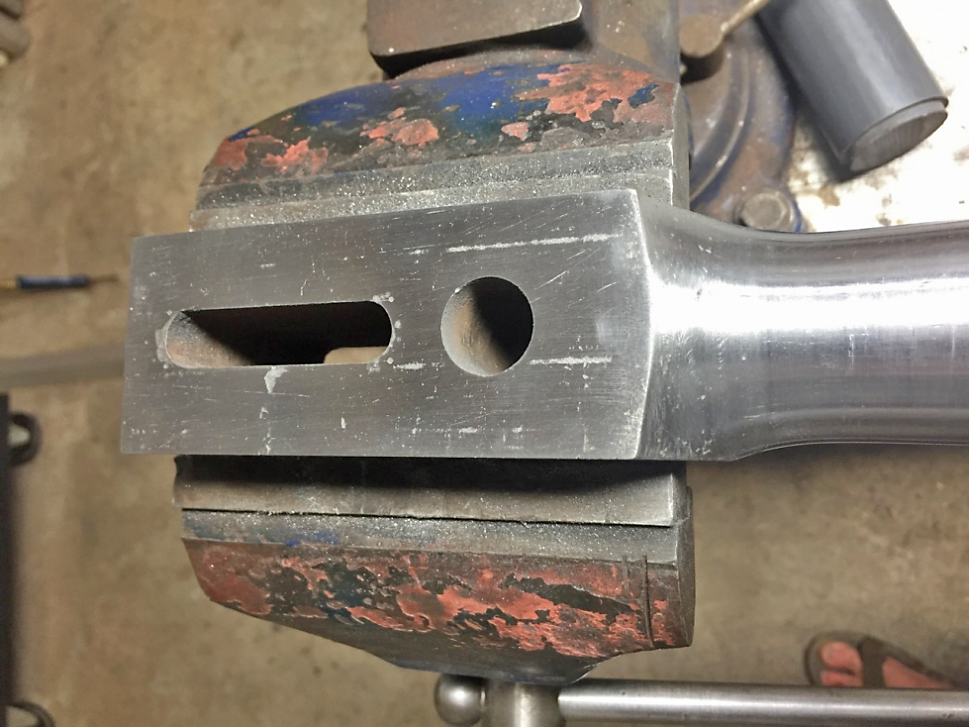
The end of a connecting rod after hand filing the flats. Notice that some marking is still apparent. The goal was to brighten and remove enough material to eliminate a significant amount of the pitting and other defects, but not so much as to make it look “new”. This method of restoration preserves some character from it’s hard-luck-life, instead of trying to pretend it is actually new, in keeping with the treatment of the rusted non-machined cast iron parts of the engine.
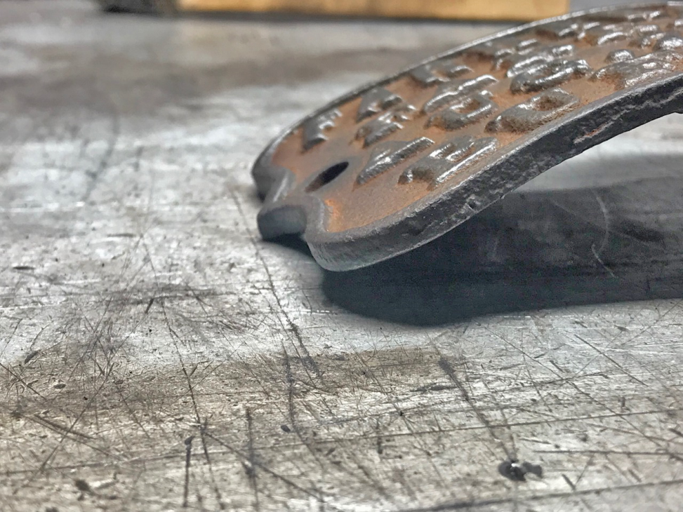
Preparing to braze a patch for a broken oil cup for one of the eccentrics used to operate the semi-rotary valve.
After brazing.
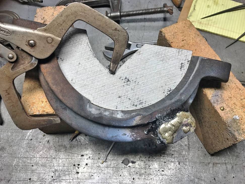
This eccentric follower was damaged. Almost half of this side of one wall that keeps it on the eccentric was broken off and had to be built up by brazing. The cement board was shaped and clamped as shown to keep the molten material off the machined surface where it wasn’t needed. I’ll CNC mill the new surface.
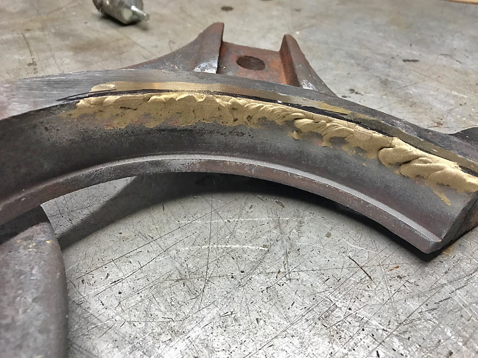
After brazing. Both pieces for the second engine had a similar chunk missing on these pieces. Both rods were bent so I suspect something at one point hit that side of the engine, breaking this area.
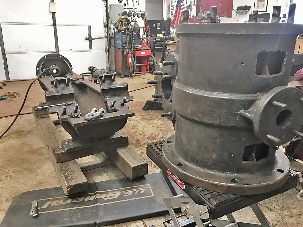
Removing the cylinder. This too will have to be bored. For this build I’ll use the cylinder from the first engine, which was already bored.
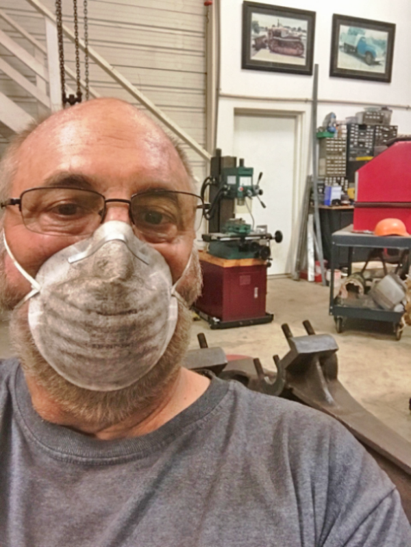
This is me in the mask during removal of rust with a wire wheel on an angle grinder and various smaller rotary wire wheels in a large die grinder. The rust sans the surface rust is very hard and the wire wheel almost polishes it. This is how you start to look when wire brushing the castings….. it got worse! The process is to wire brush the entire rusted surface with the aim of getting all the looser top layer of rust off, but not to remove all of it.
Starting to wire brush the bottom of the main casting. No trick here….. just a lot of dust to be made.
The cylinder, ready for oiling! This is AFTER filing and sanding the machined surfaces to get down to mostly bare metal….. dings and divots remain, but the machined surfaces are basically shiny base metal when done. Same is done to all fasteners. There won’t be any paint applied to these engines, as is now the preferred practice. Parts that were machined on the original will be re-machined to clean up, where possible, or filed/sanded to brighten. This process shows off the original machining skills of the mid-1800s, contrasting nicely with the buffed and oiled rust present on the castings. Both of these engines were burned when fires went through Pico Canyon.
Valve and other parts ready for assembly to the engine frame.
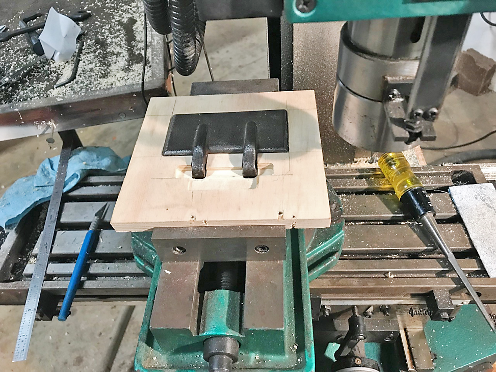
I’m missing some main bearing oil cup doors. Here I’m making a “follow board” at the parting line of one of the existing doors. I’ll have more cast, then age them with moisture, salt and dirt to rust them similar to the appearance of this one.
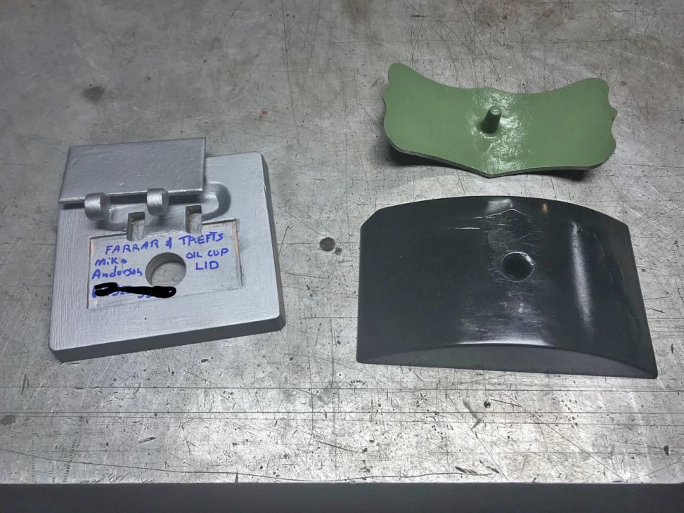
I borrowed this casting of one of the covers for the core holes on top of the cylinders. I’ve seen these on other machines that have been replaced by new ones naming the distributor or dealer who originally sold the engines. All were missing on my engines.
Patterns and follow boards for the door and the badges.
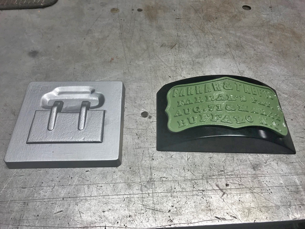
Ready for the foundry! After casting new pieces, I’ll strip the paint and filler used to prepare these castings for use as patterns, and return the badge to it’s owner.
Lots done! More to go…...
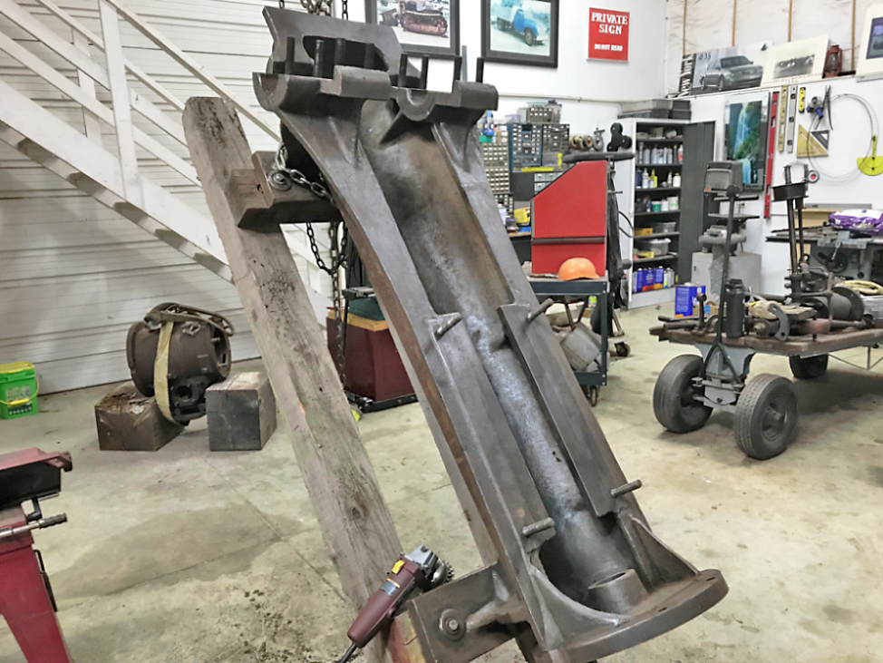
Other side of the engine. I’ve got to turn down piston and valve, machine the valve actuator, and pour babbitt bearings for the major work left. Several more minor items will have to dealt with too, but those are quickly done. My mill has been out of commission for a lot of that time, which stopped progress on the actuator.
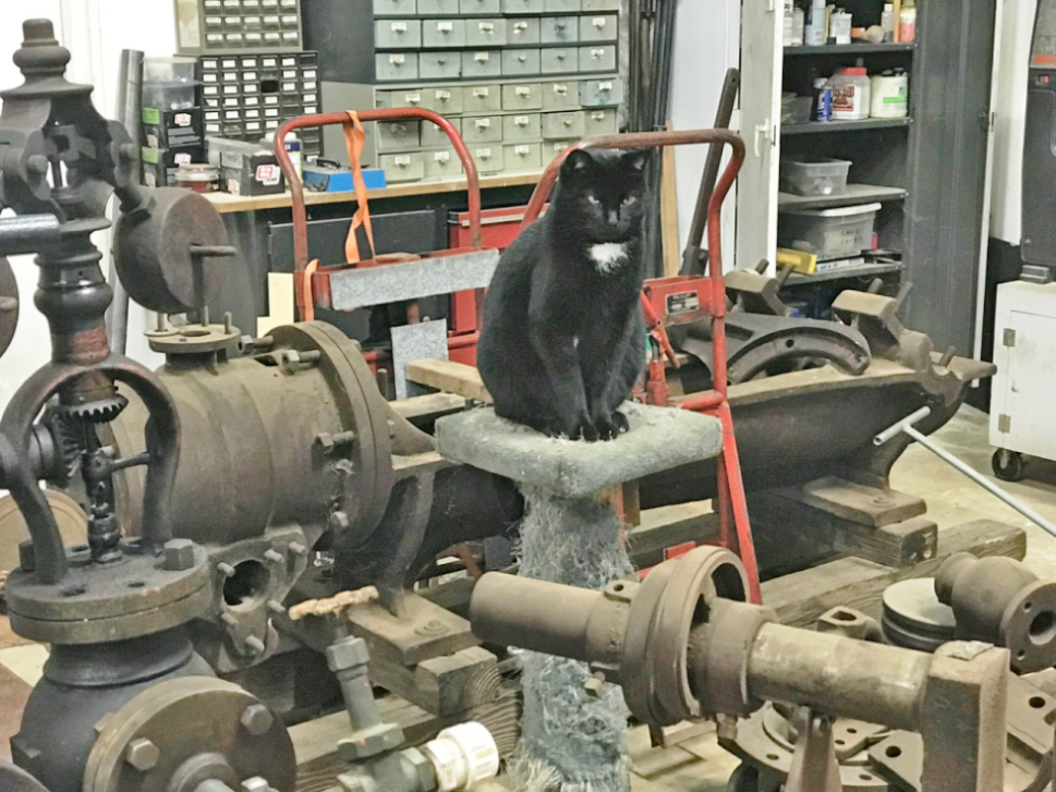
One of my inspectors, Larry, doesn’t seem too pleased with the progress so far. The fly ball governor on the left of the photo is for my Mackintosh and Hemphill steam engine…. not the F&Ts.
Kind of lost track of Mike due to covid and other issues, but the engine was finally restored.